LIU Mengmeng1, LI Shuangyang2, ZHANG Chunqiong1, WANG Boyu1, BAI Baoming,1
State Key Laboratory of Integrated Service Networks, Xidian University, Xi’an 710071, China
School of Electrical Engineering and Telecommunications, University of New South Wales, Sydney 2032, Australia
Received:2021-11-01
Fund supported:
the National Natural Science Foundation of China. 61771364 the National Key R&D Program of China. 2020YEB1807104
About authors
LIU Mengmeng received her B.S. degree in communication engineering from Xidian University, China in 2017. She is currently pursuing her Ph.D. degree with Xidian University. Her research interests include signal processing and channel coding for wireless communications.
LI Shuangyang received his B.S. and M.S. degrees from Xidian University, China in 2013 and 2016, respectively. He is currently pursuing his Ph.D. degree in Xidian University and University of New South Wales, Australia. His research interests include signal processing, channel coding and their applications to communication systems.
ZHANG Chunqiong received her B.S. degree in communication engineering from Xidian University, China in 2019. She is currently pursuing the M.S. degree with Xidian University. Her research interests include signal processing and channel coding for wireless communications.
WANG Boyu received his B.S. degree in mathematics from China University of Mining and Technology-Beijing, China in 2017, and M.S. degree in mathematics from University of Sheffield, UK in 2019. He is currently studying at Xidian University, China. His research interests include coding theory, and algorithm design and analysis via convex optimization in LDPC decoding.
BAI Baoming (bmbai@mail.xidian.edu.cn) received his B.S. degree from the Northwest Telecommunications Engineering Institute, China in 1987, and the M.S. and Ph.D. degrees in communication engineering from Xidian University, China in 1990 and 2000, respectively. From 2000 to 2003, he was a senior research assistant in the Department of Electronic Engineering, City University of Hong Kong, China. Since April 2003, he has been with the State Key Laboratory of Integrated Services Networks (ISN), School of Telecommunication Engineering, Xidian University, where he is currently a professor. In 2005, he was with the University of California, USA as a visiting scholar. His research interests include information theory and channel coding, wireless communication, and quantum communication.
E-mail:bmbai@mail.xidian.edu.cn
Abstract
Orthogonal time frequency space (OTFS) modulation is a novel two-dimensional modulation scheme for high-Doppler fading scenarios, which is implemented in the delay-Doppler (DD) domain. In time and frequency selective channels, OTFS modulation is more robust than the popular orthogonal frequency division multiplexing (OFDM) modulation technique. To further improve transmission reliability, some channel coding schemes are used in the OTFS modulation system. In this paper, the coded OTFS modulation system is considered and introduced in detail. Furthermore, the performance of the uncoded/coded OTFS system and OFDM system is analyzed with different relative speeds, modulation schemes, and iterations. Simulation results show that the OTFS system has the potential of full diversity gain and better robustness under high mobility scenarios.
LIU Mengmeng, LI Shuangyang, ZHANG Chunqiong, WANG Boyu, BAI Baoming. Coded Orthogonal Time Frequency Space Modulation. [J], 2021, 19(4): 54-62 doi:10.12142/ZTECOM.202104006
1 Introduction
The 5G network has achieved the peak rate of 10–20 Gbit/s, which is more than ten times that of 4G Long Term Evolution (LTE) cellular networks. Some new scenarios with high mobility have emerged in 5G/B5G, such as V2X (vehicle-to-vehicle—V2V and vehicle-to-infrastructure—V2I) with the terminal speed up to 300 km/h, high speed train (HST) with the maximum speed up to 500 km/h and unmanned aerial vehicle (UAV). In these cases, the higher Doppler spread will be induced. In addition, a higher data rate is required, which is considered to be solved by using a higher frequency band, such as a millimeter wave band or even a terahertz band. Both high mobility and high frequency will lead to large Doppler shifts, yielding the large frequency dispersion. Although orthogonal frequency division multiplexing (OFDM) modulation is used in 4G and 5G, it has good robustness only in time-invariant channels and is very sensitive to carrier frequency offsets. However, the channel is time-varying in high Doppler scenarios. The orthogonality of sub-carriers in an OFDM symbol is seriously damaged so that the channel estimation is no longer accurate, which will lead to severeinter-carrier interference (ICI) and the disappearance of the near-capacity advantage.
To deal with communication scenarios with high Doppler shifts, a novel two-dimensional (2D) modulation scheme called orthogonal time frequency space (OTFS) modulation was proposed by R. HADANIet al. in 2017, whose pioneering works[1–4] introduced the principle of OTFS modulation and demonstrated its significant performance on OFDM modulation in channels with high Doppler or at high frequencies. Compared with the OFDM modulation, OTFS modulation has the potential of full diversity gain and better robustness, which can effectively deal with the impact of high Doppler shifts. One more advantage of OTFS is that it can be implemented as pre- and post-processing blocks applied to a time-frequency signaling scheme, such as OFDM[5]. Furthermore, an implementation scheme of OTFS modulation based on the OFDM has been proposed in Ref. [6], which greatly reduces the complexity of implementation. In Ref. [7], the vector form of concise and elegant input-output relationship of the OFDM-based OTFS system has also been derived by utilizing the properties of the Kronecker product in matrices and vectors, which is also suitable for general time-varying channels with arbitrary Doppler and windowing functions. It is worth mentioning that this representation is very popular in subsequent research work.
As for the significant advantage of achieving the full diversity, the detailed formal analysis on the diversity order of OTFS in doubly-dispersive channels has been presented in Ref. [8], which points out that the full diversity in the delay-Doppler (DD) domain can be extracted by using the phase rotation method. In addition, when the OTFS frame is long enough, even the uncoded OTFS modulation system can obtain almost full diversity in the case of path number P = 2[9]. In order to make full use of full diversity, effective equalization is needed, which depends on the accurate channel estimation. A well-known channel estimation scheme for OTFS has been proposed in Ref. [10], in which pilots, protection symbols, and data symbols are cleverly arranged on the delay Doppler grid plane to effectively avoid the interference between pilots and data symbols at the receiver and enable the channel estimation and data detection to be performed in the same OTFS frame with the minimum overhead. However, the performance of such algorithms[10–11] is very sensitive to the availability of protection space. In fact, more advanced channel estimation methods based on compressed sensing[12], orthogonal matching pursuit (OMP)[13–14] or sparse Bayesian learning[15] algorithms have been proposed, which take advantage of the channel sparsity in the DD domain. However, the channel in the DD domain may not always be sparse, especially in the case of fractional Doppler[5]. An effective solution is to enhance channel sparsity by applying time-frequency (TF) domain windows, such as Dolph-Chebyshev (DC) window[16]. In addition, advanced detection algorithms are also an important part of OTFS to achieve potential full diversity gain[17]. A message passing algorithm (MPA) based on the maximum a posteriori probability (MAP) detection criterion has been introduced in Ref. [5], which processes the interference from other information symbols as Gaussian variables to reduce the detection complexity. However, due to the short period of the probabilistic graphical model, the proposed MPA may not converge, resulting in performance degradation. In order to solve this problem, a convergence protection receiver based on variable Bayes (VB) framework has been presented in Ref. [18], which utilizes the relative entropy to approximate the optimal detection of the corresponding a posteriori distribution to realize the MPA on a simple graphical model. In addition, a hybrid detection scheme has been demonstrated in Ref. [19], which takes the MAP and the parallel interference cancellation (PIC) into account and achieves a good trade-off between the error performance and detection complexity.
Channel coding is also one of the effective methods to ensure diversity gain and achieve reliable communications. However, most of the research work analyzes the performance of the uncoded OTFS modulation system. In Ref. [20], the BER performance of the coded OTFS system has been analyzed in detail. The derivation of pairwise-error probability (PEP) and its upper bounds have demonstrated a very interesting trade-off between the coding gain and diversity gain of the coded OTFS system. Moreover, a channel coding design criterion is derived, that is, maximizing the minimum Euclidean distance between all codeword pairs. This criterion is very similar to the channel coding design in the additive white Gaussian noise (AWGN) channel. However, the OTFS modulation experiences a time-varying channel with both time dispersion and frequency dispersion. Thus, both the inter-symbol interference (ISI) and ICI will be generated, which depend on the delay , Doppler of the channel and the cross-ambiguity function of pulses at the transmitter and receiver. The assumed ideal pulse-shaping waveforms[1, 3] that satisfy the bi-orthogonality condition in both time and frequency do not exist in practical applications. Therefore, ISI and ICI are inevitable in the actual OTFS system. Obviously, it is necessary to consider the properties of OTFS and characteristics of the DD domain channel to design the channel code suitable for the OTFS system.
In this paper, we consider the coded OTFS modulation and describe it in detail. Then, recent work about the coded OTFS system analysis is summarized. On this basis, the upper bound on the unconditional PEP of the coded OTFS system is further supplemented. In addition, the joint iterative strategy of detection and decoding is also considered to improve the system performance. According to the considered iterative system, the coding design scheme of the OTFS system is discussed. Finally, we analyze the performance of the coded/uncoded OTFS and OFDM systems with different relative speeds, modulation schemes and iterations. Simulation results show that OTFS systems have significant robustness compared with OFDM.
2 Principle and System Model
2.1 Relationship Between Time-Frequency Domain and Delay-Doppler Domain
In Ref. [4], the authors proposed that the OTFS modulation can be viewed as a time-frequency spreading scheme, which was based on the Fourier duality relation between the time-frequency plane and the delay-Doppler plane, resulting in a simple pre-processing step over an arbitrary multicarrier modulation (such as OFDM). In view of the importance of the transform between the DD domain and the TF domain, we will review this relationship in this subsection.
The grid in the TF domain and the corresponding reciprocal grid in the DD domain are shown in Fig. 1, with the size of . According to Fig. 1, the TF grid can be represented as:
,
where is the sampling interval along the time axis, is the sampling interval along the frequency axis, and and are the corresponding numbers of sampling points on the TF plane. According to the principle of the time-frequency modulation explicated in Ref. [1], the transmitted packet can be regarded as a burst one with a total duration of seconds and a total bandwidth of Hz. Then, the modulated symbols, , are transmitted over the burst packet in the TF domain.
Figure 1
Grids in time frequency (TF) plane and delay-Doppler (DD) plane
The reciprocal delay-Doppler grid is represented as:
,
where and represent the sampling intervals along the Doppler axis and the delay axis, respectively.
The mapping between signals in the TF domain and DD domain depends on two-dimensional symplectic finite Fourier transform (2D SFFT) pairs, which can be exemplified as:
,
,
where and are the responses of linear time-varying (LTV) wireless channels in the DD domain and TF domain, respectively. Without loss of generality, the DD domain representation of an LTV wireless channel can be expressed as:
,
where denotes the Dirac delta function, is the number of resolvable paths, and , and are the channel coefficient, delay and Doppler shift of the i-th path respectively. Here, and are defined as:
, .
In Eq. (6), represents the index of the delay with integer values, represents the index of the Doppler shift with integer values, and is the real number, indicating the fractional shift from the nearest Doppler index , which is also called fractional Doppler[5].
Specifically, the 2D SFFT pairs can be realized by simple discrete Fourier transform (DFT) pairs or fast Fourier transform (FFT) pairs. For example, in view of the DFT, the inverse symplectic finite Fourier transform (ISFFT) can be regarded as the M-point DFT along the delay axisand the N-point inverse DFT (IDFT) along the Doppler axis for the two-dimensional signal with the size of in the DD domain, resulting in the corresponding TF domain signal.
2.2 Coded OTFS System Model
Fig. 2 shows the proposed coded OTFS system model in this paper. Suppose that the information bit sequence of length is encoded using a forward error correction (FEC) code, resulting in the codeword of length . After interleaving, the interleaved sequence is then mapped to an M-ary signal constellation , such as M-ary phase shift keying (MPSK) or M-ary quadrature amplitude modulation (MQAM), and the modulated symbol vector of length is arranged as a two-dimensional signal matrix in the DD domain, where is the number of the sub-carriers, and is the number of time slots for each OTFS symbol. The element of the represents the modulated signals in the l-th Delay and k-th Doppler grid, for and . Then the symbol in the m-th frequency and n-th time grid is obtained by the ISFFT, which is given as:
for . The two-dimensional signal matrix in the TF domain is denoted by . The early literature[1–3] explained that the composition of the ISFFT and the windowing function in the TF domain are referred to as the OTFS transform. The window operations of the transmitter and receiver affect the cross-symbol interference of the effective impulse response[1]. The window design has the potential to increase the effective channel sparsity in the DD domain, which is conducive to the channel estimation, as described in Refs. [6] and [7]. Furthermore, the influence of the design of the TF domain window on improving the performance of the channel estimation and data detection is discussed in Ref. [16]. Here, the rectangular window is considered.
The transmitted signal in the time domain is obtained from the TF domain symbols using the Heisenberg transform parameterized by the pulse shaping filter , which can be written as:
.
This can be regarded as a general form of the OFDM modulation[3]. Moreover, OTFS modulation can be implemented as a cascade of a pre-coder (ISFFT) and a traditional OFDM modulator[6], as shown in Fig. 2.
Assume that the channel is the LTV channel described in Eq. (5), the received signal can be expressed as:
,
where is the additive white Gaussian noise with zero mean and one-sided power spectral density of .
At the receiver, is subject to the Wigner transform to obtain the received symbols in the TF domain, given by
,
where is the pulse shaping filter at the receiver. Eq. (10) can be further written as[5]:
,
where is the noise sample in the TF domain, and is the channel impulse response in the TF domain, i.e.,
.
In Eq. (12), is referred to as the cross-ambiguity function, which represents the interference between symbols in the DD domain caused by the channel dispersion[20], and can be expressed as:
.
The received symbols in the DD domain are given as:
,
for , where is the noise sample in the DD domain. Upon the received symbols , a signal detection algorithm is then performed. In addition, a joint iterative strategy between detection and decoding can also be considered.
It is generally known that the MAP detection is optimum for OTFS systems. However, the complexity of the MAP detection increases exponentially with the block size of each OTFS frame. As a compromise of the MAP detection, a lot of literature has studied the massage passing detection algorithm based on the factor graph, which can effectively reduce the detection complexity, such as Ref. [5]. For the coded system, the iterative signal processing of the detector and the decoder is usually considered at the receiver, as shown in Fig. 2. Correspondingly, soft decision detection algorithms should be adopted, such as MP, unitary approximate MP (UAMP), vector AMP (VAMP), sum-product algorithm (SPA) and other message passing algorithms. With Log-Likelihood Ratios (LLRs), the message passed from the detector to the decoder is calculated as:
where and represent the a posteriori LLRs and the priori LLRs of the detector, respectively; denotes the priori symbol probabilities, ,, and the binary vector (signal label) corresponding to can be expressed as . Similarly, the extrinsic LLRs of the decoder are also obtained by subtracting priori LLRs from the a posterioriLLRs , and is updated by the extrinsic LLRs of the detector. The iterative process between the detector and the decoder can be described as follows.
Algorithm 1. Algorithm of the iterative process between the detector and the decoder
1: Initialization: Set the number of joint iterations , the maximum number of joint iterations , the maximum number of detection iterations , the maximum number of decoding iterations , and the priori LLRs
2: whiledo
3: Perform detection until is satisfied.
4: Calculate the a posteriori LLRs and the extrinsic LLRs of the detector for all ,,
5: Convert the symbol form of into the bit form ,
6: Deinterleave the extrinsic LLRs , resulting in
7: Set ,
8: Perform decoding until is satisfied
9: Calculate the a posteriori LLRs and the extrinsic LLRs of the decoder for
10: if then
11: Interleave the extrinsic LLRs , resulting in
12: Convert the bit form of into the symbol form
13: Set
14: end if
15:
16: end while
17: Make decisions of according to the a posteriori LLRs for
2.3 Vectorization Representation of the System
With respect to the vectorization, the following definitions are given, , ,
, and , where denotes the vectorized version of the 2D matrix formed by stacking the columns of the one into a single column vector. Besides, the N-point DFT matrix and its inverse are represented by and respectively and are assumed to be normalized so that . According to the introduction of the coded OTFS system in the above subsection, the relationship between the symbol matrix in the TF domain and in the DD domain can be described as:
.
The vectorized form can be expressed as:
.
Considering that the pulse shaping filter is the rectangular form, the output of the Heisenberg transform is given by
,
where represents the transmitted signal matrix in the time domain. Vectorize by stacking each column of into a vector, we have
.
At the receiver, the received signal expressed by Eq. (9) in discrete form is
,
where indicates mod MN operation, , and are the corresponding discrete forms of , and , respectively. Thus, the received signal can be written in the vector form as
.
In the above formula, is an matrix, given by Ref. [10],
,
where is the permutation matrix (forward cyclic shift), and is the diagonal matrix, as shown below.
,
.
The received signal vector is devectorized into an matrix . Then, the Wigner transform and SFFT can be successive to obtain the received signal matrix with the size in the DD domain as follows:
.
The vector form can be obtained by
.
Substituting Eqs. (19) and (21) with Eq. (26), we can get the vector form of the input-output relation in the DD domain as follows:
The vectorized forms of each operation are simple and more vivid, which contribute to understanding the OTFS modulation more clearly and they are widely used in the research of the OTFS modulation.
3 Error Performance of the Coded OTFS System
3.1 Error Performance Analysis
PEP is commonly used in communication systems for analyzing the error performance of the system. In Ref. [8], the achievable diversity order of the OTFS system is analyzed based on the PEP under the maximum likelihood (ML) detection. Similarly, the PEP under the ML detection is also used to analyze the error performance of OTFS modulation in Ref. [21]. On this basis, the effective diversity (ED) is introduced from the perspective of PEP[9]. In Ref. [20], the conditional PEP and the unconditional PEP are utilized to analyze the error performance of coded OTFS systems. And an approximate upper bound on the unconditional PEP for small P is derived by:
,
where is the codeword difference vector, is the squared Euclidean distance between and , and r is the rank of the positive semidefinite Hermite matrix given by Eq. (18)[20]. In Eq. (28), the exponent r and the term are regarded as the diversity gain and the coding gain, respectively. According to the early works, e.g. Refs. [1] and [8], OTFS can achieve full diversity, whose order is the number of the separable multipath P. When the channel code is given, the term is also fixed. Thus, as described in Corollary 1 in Ref. [20], the diversity gain increases and the coding gain decreases with the increase of P, which reveals an interesting trade-off between them. In addition, an approximate upper bound on the unconditional PEP for large P is also given by
,
which only depends on the signal to noise ratio (SNR) and , and demonstrates that channels with a large number of resolvable paths approach an AWGN model.
More detailed derivation and illustration can be found in Ref. [20]. It should be noted that the upper bound on the unconditional PEP shown in Eqs. (28) and (29) are approximate. Referring to the appendix A in Ref. [22], the upper bound on the unconditional PEP has a more accurate display.
Note that is also a Gram matrix[23] corresponding to vectors , where , and . According to the appendix A in Ref. [22] , the determinant of Gram matrix can be calculated by
where is the orthogonal projection of onto the orthogonal complement of span . Besides, the maximum value of the rank of the matrix is the number of resolvable paths P. In particular, when matrix is full-rank, we have . Then the upper bound on the unconditional PEP of the coded OTFS system can be rewritten as
,
Furthermore, the equality holds if is a diagonal matrix.
3.2 Design Issues of Channel Codes for OTFS Systems
In Ref. [20], the code design criterion for the coded OTFS is given based on the PEP analysis, which is to maximize the minimum squared Euclidean distance of all possible codeword pairs. Simulation results show the performance of the coded OTFS system under convolutional codes with different minimum squared Euclidean distances and verify the proposed code design criterion. At present, most channel codes are designed for AWGN channels. In Ref. [20], authors also reveal that the channel with a large number of diversity paths approaches an AWGN channel when the number of resolvable paths P is large enough. In this case, some good channel codes can be used in the OTFS system. However, the increase of P will bring about large ISI, making signal detection more complicated. Therefore, it is necessary to design channel codes according to the characteristics of the OTFS modulation. In particular, the joint iteration between decoding and detection is needed, when the channel conditions are poor. In a word, the design of the channel coding scheme is still an interesting challenge.
A simple and direct method to analyze coded OTFS systems is to use the extrinsic information transfer (EXIT) chart[24], which is commonly used to aid the construction of good iteratively-decoded error-correcting codes. EXIT charts are especially popular in the analysis of low-density parity-check (LDPC) codes and Turbo codes. In the most works of coded OFDM systems, the tool, EXIT chart, is also commonly utilized to optimize the performance of iterative decoding, and parameters of the corresponding channel coding scheme and detection, such as Refs. [25–26].
Another possible method is to learn from the code construction method under ISI channels. In general, ISI channels can be conveniently represented by a trellis[27] or a factor graph[28]. Codes such as Turbo codes and LDPC codes can also be represented by a trellis or a factor graph. Note this, the channel factor graph and the code factor graph are considered together to obtain the joint channel/code graph in Ref. [29]. The limits of the performance of LDPC codes over binary linear ISI channels are also studied in Ref. [29]. With the use of density evolution, the noise tolerance threshold is calculated. This may provide some reference for the design of coded OTFS system, because the received signals with ISI can also be represented by a trellis or a factor graph.
4 Numerical Results
Numerical results of the considered coded OTFS system are provided in this section. The 5G LDPC code is used, whose code rate and length of information sequence are and , respectively. Without loss of generality, quadrature phase shift keying (QPSK) and 16QAM are chosen as the traditional modulation schemes, whose corresponding OTFS frame sizes are and , respectively. In all simulations, the LTV channel with path number is used, where the path gain follows the Rayleigh distribution with respect to the exponential power delay profile. For the DD domain channel, the indices of delay and Doppler shifts are integers. Moreover, according to 4G LTE and 5G NR, the carrier frequency and subcarrier interval are selected as 4 GHz and 15 kHz, respectively. Thus, we consider the maximum delay index and the maximum Doppler shift index , corresponding to the cases in which relative speeds are around 275 km/h, 500 km/h, and 750 km/h, respectively. It should be noted that the delay and Doppler shift indices are generated uniformly at random. At the receiver, the near-optimal symbol-by-symbol MAP detection algorithm[19] is used, unless otherwise specified. In order to accelerate the iterative convergence between the detector and the decoder, the offset min-sum algorithm (MSA) with an offset factor of 0.5 is adopted by the decoder. The maximum iteration number of the detection is 10, while that of the decoding is 50.
Fig. 3 shows the frame error rate (FER) performances of the uncoded OTFS and OFDM systems with 16QAM and different relative speeds, such as 275 km/h, 500 km/h and 750 km/h. For a fair comparison, we also apply the near-optimal symbol-by-symbol MAP detection[19] for OFDM systems, which is designed to exploit all the interference (including both ISI and ICI). Unless otherwise specified, this detection algorithm will be used in subsequent simulations of uncoded/coded OFDM systems. As shown in Fig. 3, we first observe that both uncoded OTFS and OFDM systems have good robustness at different relative speeds. This is because the channel coherence time ( ms corresponding to relative speeds of 275 km/h, 500 km/h and 750 km/h, respectively) is longer than the OFDM symbol time ( ms). The channel variation is slow at considered relative speeds, and the interference between adjacent subcarriers demonstrates similar property. It is also assumed that the channel state information is perfectly known to the receiver. Thus, with the use of the near-optimal symbol-by-symbol MAP detection, all the ISI and ICI can be effectively cancelled. Furthermore, the error performances for OFDM transmission with considered relative speeds are similar. On the other hand, for OTFS transmission, different Doppler shifts caused by different relative speeds do not change the 2D convolution nature of the signal-channel interaction in the DD domain. Therefore, OTFS is insensitive to Doppler effects. In addition, we notice that the OTFS system has a better error performance than the corresponding OFDM system. Moreover, the slope of the FER curve for the OTFS system is greatly higher than that for the OFDM system, which indicates that OTFS enjoys a larger diversity advantage. Those observations align with the findings in Refs. [5] and [20].
Figure 3
FER performance of uncoded OTFS and OFDM systems with 16QAM, where relative speeds are 275 km/h, 500 km/h, and 750 km/h respectively
The FER performances of the coded OTFS and OFDM systems without the joint iteration are also shown in Fig. 4, where the relative speeds are 275 km/h, 500 km/h, and 750 km/h, respectively. The 16QAM modulated symbols are considered in the simulation. Similar to Fig. 3, we observe that the FER performances of both coded OTFS and OFDM systems do not change much with different relative speeds, thanks to the near-optimal MAP detection. Furthermore, compared with uncoded cases, both coded OTFS and OFDM systems enjoy an improved error performance. In addition, we also notice that the error performance of the coded OTFS is much better than that of the coded OFDM. However, it can be noticed that the coding improvement for the OFDM system is more significant compared with that of the OTFS system. Moreover, the FER curve of the coded OFDM system shares almost the same slope as that of the coded OTFS system. This is because OTFS has the potential to achieve the full channel diversity and consequently, channel coding cannot improve the diversity performance very much for OTFS systems. In contrast, OFDM systems rely deeply on the channel coding to achieve the larger diversity gain. Those observations are also consistent with the analysis in Ref. [20].
Figure 4
FER performance of coded OTFS and OFDM systems with 16QAM, where relative speeds are 275 km/h, 500 km/h, and 750 km/h respectively
The FER performance of the coded OTFS system with different joint detection and decoding iterations is compared in Fig. 5, as well as the uncoded OTFS system. The modulation type is QPSK and the relative speed is 500 km/h in the simulation. We can obviously observe that the channel coding significantly improves the error performance. In addition, we notice that the iterations between the detector and decoder do not improve the error performance very much. This is because the near-optimal symbol-by-symbol MAP detection algorithm used in the coded OTFS system exploits all possible interference patterns, and therefore the a priori information from channel decoding cannot improve the extrinsic information from the near-optimal detection for decoding. Consequently, the iterations between the detector and decoder cannot improve the error performance very much.
Figure 5
FER performance of coded OTFS system with different iterations between detection and decoding, where QPSK and relative speed 500 km/h are considered
5 Conclusions
In this paper, the coded OTFS system is introduced and the existing research work of the coded OTFS is summarized. Based on this, the upper bound on unconditional PEP for the coded OTFS system is supplemented, and the design issues of the channel coding scheme are discussed. Furthermore, the performance of the uncoded OTFS and OFDM systems is analyzed, as well as that of 5G LDPC coded systems. Simulation results show that the performance of the OTFS system significantly outperforms that of OFDM system under different speeds, modulation schemes and iterations, whether coded or uncoded.
... To deal with communication scenarios with high Doppler shifts, a novel two-dimensional (2D) modulation scheme called orthogonal time frequency space (OTFS) modulation was proposed by R. HADANIet al. in 2017, whose pioneering works[1–4] introduced the principle of OTFS modulation and demonstrated its significant performance on OFDM modulation in channels with high Doppler or at high frequencies. Compared with the OFDM modulation, OTFS modulation has the potential of full diversity gain and better robustness, which can effectively deal with the impact of high Doppler shifts. One more advantage of OTFS is that it can be implemented as pre- and post-processing blocks applied to a time-frequency signaling scheme, such as OFDM[5]. Furthermore, an implementation scheme of OTFS modulation based on the OFDM has been proposed in Ref. [6], which greatly reduces the complexity of implementation. In Ref. [7], the vector form of concise and elegant input-output relationship of the OFDM-based OTFS system has also been derived by utilizing the properties of the Kronecker product in matrices and vectors, which is also suitable for general time-varying channels with arbitrary Doppler and windowing functions. It is worth mentioning that this representation is very popular in subsequent research work. ...
... Channel coding is also one of the effective methods to ensure diversity gain and achieve reliable communications. However, most of the research work analyzes the performance of the uncoded OTFS modulation system. In Ref. [20], the BER performance of the coded OTFS system has been analyzed in detail. The derivation of pairwise-error probability (PEP) and its upper bounds have demonstrated a very interesting trade-off between the coding gain and diversity gain of the coded OTFS system. Moreover, a channel coding design criterion is derived, that is, maximizing the minimum Euclidean distance between all codeword pairs. This criterion is very similar to the channel coding design in the additive white Gaussian noise (AWGN) channel. However, the OTFS modulation experiences a time-varying channel with both time dispersion and frequency dispersion. Thus, both the inter-symbol interference (ISI) and ICI will be generated, which depend on the delay , Doppler of the channel and the cross-ambiguity function of pulses at the transmitter and receiver. The assumed ideal pulse-shaping waveforms[1, 3] that satisfy the bi-orthogonality condition in both time and frequency do not exist in practical applications. Therefore, ISI and ICI are inevitable in the actual OTFS system. Obviously, it is necessary to consider the properties of OTFS and characteristics of the DD domain channel to design the channel code suitable for the OTFS system. ...
... where is the sampling interval along the time axis, is the sampling interval along the frequency axis, and and are the corresponding numbers of sampling points on the TF plane. According to the principle of the time-frequency modulation explicated in Ref. [1], the transmitted packet can be regarded as a burst one with a total duration of seconds and a total bandwidth of Hz. Then, the modulated symbols, , are transmitted over the burst packet in the TF domain. ...
... for . The two-dimensional signal matrix in the TF domain is denoted by . The early literature[1–3] explained that the composition of the ISFFT and the windowing function in the TF domain are referred to as the OTFS transform. The window operations of the transmitter and receiver affect the cross-symbol interference of the effective impulse response[1]. The window design has the potential to increase the effective channel sparsity in the DD domain, which is conducive to the channel estimation, as described in Refs. [6] and [7]. Furthermore, the influence of the design of the TF domain window on improving the performance of the channel estimation and data detection is discussed in Ref. [16]. Here, the rectangular window is considered. ...
... [1]. The window design has the potential to increase the effective channel sparsity in the DD domain, which is conducive to the channel estimation, as described in Refs. [6] and [7]. Furthermore, the influence of the design of the TF domain window on improving the performance of the channel estimation and data detection is discussed in Ref. [16]. Here, the rectangular window is considered. ...
... where is the codeword difference vector, is the squared Euclidean distance between and , and r is the rank of the positive semidefinite Hermite matrix given by Eq. (18)[20]. In Eq. (28), the exponent r and the term are regarded as the diversity gain and the coding gain, respectively. According to the early works, e.g. Refs. [1] and [8], OTFS can achieve full diversity, whose order is the number of the separable multipath P. When the channel code is given, the term is also fixed. Thus, as described in Corollary 1 in Ref. [20], the diversity gain increases and the coding gain decreases with the increase of P, which reveals an interesting trade-off between them. In addition, an approximate upper bound on the unconditional PEP for large P is also given by ...
Orthogonal Time Frequency Space (OTFS) modulation for millimeter-wave communications systems
0
2017
Orthogonal time frequency space modulation
3
2017
... Channel coding is also one of the effective methods to ensure diversity gain and achieve reliable communications. However, most of the research work analyzes the performance of the uncoded OTFS modulation system. In Ref. [20], the BER performance of the coded OTFS system has been analyzed in detail. The derivation of pairwise-error probability (PEP) and its upper bounds have demonstrated a very interesting trade-off between the coding gain and diversity gain of the coded OTFS system. Moreover, a channel coding design criterion is derived, that is, maximizing the minimum Euclidean distance between all codeword pairs. This criterion is very similar to the channel coding design in the additive white Gaussian noise (AWGN) channel. However, the OTFS modulation experiences a time-varying channel with both time dispersion and frequency dispersion. Thus, both the inter-symbol interference (ISI) and ICI will be generated, which depend on the delay , Doppler of the channel and the cross-ambiguity function of pulses at the transmitter and receiver. The assumed ideal pulse-shaping waveforms[1, 3] that satisfy the bi-orthogonality condition in both time and frequency do not exist in practical applications. Therefore, ISI and ICI are inevitable in the actual OTFS system. Obviously, it is necessary to consider the properties of OTFS and characteristics of the DD domain channel to design the channel code suitable for the OTFS system. ...
... for . The two-dimensional signal matrix in the TF domain is denoted by . The early literature[1–3] explained that the composition of the ISFFT and the windowing function in the TF domain are referred to as the OTFS transform. The window operations of the transmitter and receiver affect the cross-symbol interference of the effective impulse response[1]. The window design has the potential to increase the effective channel sparsity in the DD domain, which is conducive to the channel estimation, as described in Refs. [6] and [7]. Furthermore, the influence of the design of the TF domain window on improving the performance of the channel estimation and data detection is discussed in Ref. [16]. Here, the rectangular window is considered. ...
... This can be regarded as a general form of the OFDM modulation[3]. Moreover, OTFS modulation can be implemented as a cascade of a pre-coder (ISFFT) and a traditional OFDM modulator[6], as shown in Fig. 2. ...
OTFS: A new generation of modulation addressing the challenges of
2
... To deal with communication scenarios with high Doppler shifts, a novel two-dimensional (2D) modulation scheme called orthogonal time frequency space (OTFS) modulation was proposed by R. HADANIet al. in 2017, whose pioneering works[1–4] introduced the principle of OTFS modulation and demonstrated its significant performance on OFDM modulation in channels with high Doppler or at high frequencies. Compared with the OFDM modulation, OTFS modulation has the potential of full diversity gain and better robustness, which can effectively deal with the impact of high Doppler shifts. One more advantage of OTFS is that it can be implemented as pre- and post-processing blocks applied to a time-frequency signaling scheme, such as OFDM[5]. Furthermore, an implementation scheme of OTFS modulation based on the OFDM has been proposed in Ref. [6], which greatly reduces the complexity of implementation. In Ref. [7], the vector form of concise and elegant input-output relationship of the OFDM-based OTFS system has also been derived by utilizing the properties of the Kronecker product in matrices and vectors, which is also suitable for general time-varying channels with arbitrary Doppler and windowing functions. It is worth mentioning that this representation is very popular in subsequent research work. ...
... In Ref. [4], the authors proposed that the OTFS modulation can be viewed as a time-frequency spreading scheme, which was based on the Fourier duality relation between the time-frequency plane and the delay-Doppler plane, resulting in a simple pre-processing step over an arbitrary multicarrier modulation (such as OFDM). In view of the importance of the transform between the DD domain and the TF domain, we will review this relationship in this subsection. ...
Interference cancellation and iterative detection for orthogonal time frequency space modulation
7
2018
... To deal with communication scenarios with high Doppler shifts, a novel two-dimensional (2D) modulation scheme called orthogonal time frequency space (OTFS) modulation was proposed by R. HADANIet al. in 2017, whose pioneering works[1–4] introduced the principle of OTFS modulation and demonstrated its significant performance on OFDM modulation in channels with high Doppler or at high frequencies. Compared with the OFDM modulation, OTFS modulation has the potential of full diversity gain and better robustness, which can effectively deal with the impact of high Doppler shifts. One more advantage of OTFS is that it can be implemented as pre- and post-processing blocks applied to a time-frequency signaling scheme, such as OFDM[5]. Furthermore, an implementation scheme of OTFS modulation based on the OFDM has been proposed in Ref. [6], which greatly reduces the complexity of implementation. In Ref. [7], the vector form of concise and elegant input-output relationship of the OFDM-based OTFS system has also been derived by utilizing the properties of the Kronecker product in matrices and vectors, which is also suitable for general time-varying channels with arbitrary Doppler and windowing functions. It is worth mentioning that this representation is very popular in subsequent research work. ...
... As for the significant advantage of achieving the full diversity, the detailed formal analysis on the diversity order of OTFS in doubly-dispersive channels has been presented in Ref. [8], which points out that the full diversity in the delay-Doppler (DD) domain can be extracted by using the phase rotation method. In addition, when the OTFS frame is long enough, even the uncoded OTFS modulation system can obtain almost full diversity in the case of path number P = 2[9]. In order to make full use of full diversity, effective equalization is needed, which depends on the accurate channel estimation. A well-known channel estimation scheme for OTFS has been proposed in Ref. [10], in which pilots, protection symbols, and data symbols are cleverly arranged on the delay Doppler grid plane to effectively avoid the interference between pilots and data symbols at the receiver and enable the channel estimation and data detection to be performed in the same OTFS frame with the minimum overhead. However, the performance of such algorithms[10–11] is very sensitive to the availability of protection space. In fact, more advanced channel estimation methods based on compressed sensing[12], orthogonal matching pursuit (OMP)[13–14] or sparse Bayesian learning[15] algorithms have been proposed, which take advantage of the channel sparsity in the DD domain. However, the channel in the DD domain may not always be sparse, especially in the case of fractional Doppler[5]. An effective solution is to enhance channel sparsity by applying time-frequency (TF) domain windows, such as Dolph-Chebyshev (DC) window[16]. In addition, advanced detection algorithms are also an important part of OTFS to achieve potential full diversity gain[17]. A message passing algorithm (MPA) based on the maximum a posteriori probability (MAP) detection criterion has been introduced in Ref. [5], which processes the interference from other information symbols as Gaussian variables to reduce the detection complexity. However, due to the short period of the probabilistic graphical model, the proposed MPA may not converge, resulting in performance degradation. In order to solve this problem, a convergence protection receiver based on variable Bayes (VB) framework has been presented in Ref. [18], which utilizes the relative entropy to approximate the optimal detection of the corresponding a posteriori distribution to realize the MPA on a simple graphical model. In addition, a hybrid detection scheme has been demonstrated in Ref. [19], which takes the MAP and the parallel interference cancellation (PIC) into account and achieves a good trade-off between the error performance and detection complexity. ...
... . A message passing algorithm (MPA) based on the maximum a posteriori probability (MAP) detection criterion has been introduced in Ref. [5], which processes the interference from other information symbols as Gaussian variables to reduce the detection complexity. However, due to the short period of the probabilistic graphical model, the proposed MPA may not converge, resulting in performance degradation. In order to solve this problem, a convergence protection receiver based on variable Bayes (VB) framework has been presented in Ref. [18], which utilizes the relative entropy to approximate the optimal detection of the corresponding a posteriori distribution to realize the MPA on a simple graphical model. In addition, a hybrid detection scheme has been demonstrated in Ref. [19], which takes the MAP and the parallel interference cancellation (PIC) into account and achieves a good trade-off between the error performance and detection complexity. ...
... In Eq. (6), represents the index of the delay with integer values, represents the index of the Doppler shift with integer values, and is the real number, indicating the fractional shift from the nearest Doppler index , which is also called fractional Doppler[5]. ...
... where is the pulse shaping filter at the receiver. Eq. (10) can be further written as[5]: ...
... It is generally known that the MAP detection is optimum for OTFS systems. However, the complexity of the MAP detection increases exponentially with the block size of each OTFS frame. As a compromise of the MAP detection, a lot of literature has studied the massage passing detection algorithm based on the factor graph, which can effectively reduce the detection complexity, such as Ref. [5]. For the coded system, the iterative signal processing of the detector and the decoder is usually considered at the receiver, as shown in Fig. 2. Correspondingly, soft decision detection algorithms should be adopted, such as MP, unitary approximate MP (UAMP), vector AMP (VAMP), sum-product algorithm (SPA) and other message passing algorithms. With Log-Likelihood Ratios (LLRs), the message passed from the detector to the decoder is calculated as: ...
... Fig. 3 shows the frame error rate (FER) performances of the uncoded OTFS and OFDM systems with 16QAM and different relative speeds, such as 275 km/h, 500 km/h and 750 km/h. For a fair comparison, we also apply the near-optimal symbol-by-symbol MAP detection[19] for OFDM systems, which is designed to exploit all the interference (including both ISI and ICI). Unless otherwise specified, this detection algorithm will be used in subsequent simulations of uncoded/coded OFDM systems. As shown in Fig. 3, we first observe that both uncoded OTFS and OFDM systems have good robustness at different relative speeds. This is because the channel coherence time ( ms corresponding to relative speeds of 275 km/h, 500 km/h and 750 km/h, respectively) is longer than the OFDM symbol time ( ms). The channel variation is slow at considered relative speeds, and the interference between adjacent subcarriers demonstrates similar property. It is also assumed that the channel state information is perfectly known to the receiver. Thus, with the use of the near-optimal symbol-by-symbol MAP detection, all the ISI and ICI can be effectively cancelled. Furthermore, the error performances for OFDM transmission with considered relative speeds are similar. On the other hand, for OTFS transmission, different Doppler shifts caused by different relative speeds do not change the 2D convolution nature of the signal-channel interaction in the DD domain. Therefore, OTFS is insensitive to Doppler effects. In addition, we notice that the OTFS system has a better error performance than the corresponding OFDM system. Moreover, the slope of the FER curve for the OTFS system is greatly higher than that for the OFDM system, which indicates that OTFS enjoys a larger diversity advantage. Those observations align with the findings in Refs. [5] and [20]. ...
Low complexity modem structure for OFDM-based orthogonal time frequency space modulation
3
2018
... To deal with communication scenarios with high Doppler shifts, a novel two-dimensional (2D) modulation scheme called orthogonal time frequency space (OTFS) modulation was proposed by R. HADANIet al. in 2017, whose pioneering works[1–4] introduced the principle of OTFS modulation and demonstrated its significant performance on OFDM modulation in channels with high Doppler or at high frequencies. Compared with the OFDM modulation, OTFS modulation has the potential of full diversity gain and better robustness, which can effectively deal with the impact of high Doppler shifts. One more advantage of OTFS is that it can be implemented as pre- and post-processing blocks applied to a time-frequency signaling scheme, such as OFDM[5]. Furthermore, an implementation scheme of OTFS modulation based on the OFDM has been proposed in Ref. [6], which greatly reduces the complexity of implementation. In Ref. [7], the vector form of concise and elegant input-output relationship of the OFDM-based OTFS system has also been derived by utilizing the properties of the Kronecker product in matrices and vectors, which is also suitable for general time-varying channels with arbitrary Doppler and windowing functions. It is worth mentioning that this representation is very popular in subsequent research work. ...
... for . The two-dimensional signal matrix in the TF domain is denoted by . The early literature[1–3] explained that the composition of the ISFFT and the windowing function in the TF domain are referred to as the OTFS transform. The window operations of the transmitter and receiver affect the cross-symbol interference of the effective impulse response[1]. The window design has the potential to increase the effective channel sparsity in the DD domain, which is conducive to the channel estimation, as described in Refs. [6] and [7]. Furthermore, the influence of the design of the TF domain window on improving the performance of the channel estimation and data detection is discussed in Ref. [16]. Here, the rectangular window is considered. ...
... This can be regarded as a general form of the OFDM modulation[3]. Moreover, OTFS modulation can be implemented as a cascade of a pre-coder (ISFFT) and a traditional OFDM modulator[6], as shown in Fig. 2. ...
Analysis of discrete-time MIMO OFDM-based orthogonal time frequency space modulation
2
2018
... To deal with communication scenarios with high Doppler shifts, a novel two-dimensional (2D) modulation scheme called orthogonal time frequency space (OTFS) modulation was proposed by R. HADANIet al. in 2017, whose pioneering works[1–4] introduced the principle of OTFS modulation and demonstrated its significant performance on OFDM modulation in channels with high Doppler or at high frequencies. Compared with the OFDM modulation, OTFS modulation has the potential of full diversity gain and better robustness, which can effectively deal with the impact of high Doppler shifts. One more advantage of OTFS is that it can be implemented as pre- and post-processing blocks applied to a time-frequency signaling scheme, such as OFDM[5]. Furthermore, an implementation scheme of OTFS modulation based on the OFDM has been proposed in Ref. [6], which greatly reduces the complexity of implementation. In Ref. [7], the vector form of concise and elegant input-output relationship of the OFDM-based OTFS system has also been derived by utilizing the properties of the Kronecker product in matrices and vectors, which is also suitable for general time-varying channels with arbitrary Doppler and windowing functions. It is worth mentioning that this representation is very popular in subsequent research work. ...
... for . The two-dimensional signal matrix in the TF domain is denoted by . The early literature[1–3] explained that the composition of the ISFFT and the windowing function in the TF domain are referred to as the OTFS transform. The window operations of the transmitter and receiver affect the cross-symbol interference of the effective impulse response[1]. The window design has the potential to increase the effective channel sparsity in the DD domain, which is conducive to the channel estimation, as described in Refs. [6] and [7]. Furthermore, the influence of the design of the TF domain window on improving the performance of the channel estimation and data detection is discussed in Ref. [16]. Here, the rectangular window is considered. ...
On the diversity of uncoded OTFS modulation in doubly-dispersive channels
3
2019
... As for the significant advantage of achieving the full diversity, the detailed formal analysis on the diversity order of OTFS in doubly-dispersive channels has been presented in Ref. [8], which points out that the full diversity in the delay-Doppler (DD) domain can be extracted by using the phase rotation method. In addition, when the OTFS frame is long enough, even the uncoded OTFS modulation system can obtain almost full diversity in the case of path number P = 2[9]. In order to make full use of full diversity, effective equalization is needed, which depends on the accurate channel estimation. A well-known channel estimation scheme for OTFS has been proposed in Ref. [10], in which pilots, protection symbols, and data symbols are cleverly arranged on the delay Doppler grid plane to effectively avoid the interference between pilots and data symbols at the receiver and enable the channel estimation and data detection to be performed in the same OTFS frame with the minimum overhead. However, the performance of such algorithms[10–11] is very sensitive to the availability of protection space. In fact, more advanced channel estimation methods based on compressed sensing[12], orthogonal matching pursuit (OMP)[13–14] or sparse Bayesian learning[15] algorithms have been proposed, which take advantage of the channel sparsity in the DD domain. However, the channel in the DD domain may not always be sparse, especially in the case of fractional Doppler[5]. An effective solution is to enhance channel sparsity by applying time-frequency (TF) domain windows, such as Dolph-Chebyshev (DC) window[16]. In addition, advanced detection algorithms are also an important part of OTFS to achieve potential full diversity gain[17]. A message passing algorithm (MPA) based on the maximum a posteriori probability (MAP) detection criterion has been introduced in Ref. [5], which processes the interference from other information symbols as Gaussian variables to reduce the detection complexity. However, due to the short period of the probabilistic graphical model, the proposed MPA may not converge, resulting in performance degradation. In order to solve this problem, a convergence protection receiver based on variable Bayes (VB) framework has been presented in Ref. [18], which utilizes the relative entropy to approximate the optimal detection of the corresponding a posteriori distribution to realize the MPA on a simple graphical model. In addition, a hybrid detection scheme has been demonstrated in Ref. [19], which takes the MAP and the parallel interference cancellation (PIC) into account and achieves a good trade-off between the error performance and detection complexity. ...
... PEP is commonly used in communication systems for analyzing the error performance of the system. In Ref. [8], the achievable diversity order of the OTFS system is analyzed based on the PEP under the maximum likelihood (ML) detection. Similarly, the PEP under the ML detection is also used to analyze the error performance of OTFS modulation in Ref. [21]. On this basis, the effective diversity (ED) is introduced from the perspective of PEP[9]. In Ref. [20], the conditional PEP and the unconditional PEP are utilized to analyze the error performance of coded OTFS systems. And an approximate upper bound on the unconditional PEP for small P is derived by: ...
... where is the codeword difference vector, is the squared Euclidean distance between and , and r is the rank of the positive semidefinite Hermite matrix given by Eq. (18)[20]. In Eq. (28), the exponent r and the term are regarded as the diversity gain and the coding gain, respectively. According to the early works, e.g. Refs. [1] and [8], OTFS can achieve full diversity, whose order is the number of the separable multipath P. When the channel code is given, the term is also fixed. Thus, as described in Corollary 1 in Ref. [20], the diversity gain increases and the coding gain decreases with the increase of P, which reveals an interesting trade-off between them. In addition, an approximate upper bound on the unconditional PEP for large P is also given by ...
Effective diversity of OTFS modulation
2
2020
... As for the significant advantage of achieving the full diversity, the detailed formal analysis on the diversity order of OTFS in doubly-dispersive channels has been presented in Ref. [8], which points out that the full diversity in the delay-Doppler (DD) domain can be extracted by using the phase rotation method. In addition, when the OTFS frame is long enough, even the uncoded OTFS modulation system can obtain almost full diversity in the case of path number P = 2[9]. In order to make full use of full diversity, effective equalization is needed, which depends on the accurate channel estimation. A well-known channel estimation scheme for OTFS has been proposed in Ref. [10], in which pilots, protection symbols, and data symbols are cleverly arranged on the delay Doppler grid plane to effectively avoid the interference between pilots and data symbols at the receiver and enable the channel estimation and data detection to be performed in the same OTFS frame with the minimum overhead. However, the performance of such algorithms[10–11] is very sensitive to the availability of protection space. In fact, more advanced channel estimation methods based on compressed sensing[12], orthogonal matching pursuit (OMP)[13–14] or sparse Bayesian learning[15] algorithms have been proposed, which take advantage of the channel sparsity in the DD domain. However, the channel in the DD domain may not always be sparse, especially in the case of fractional Doppler[5]. An effective solution is to enhance channel sparsity by applying time-frequency (TF) domain windows, such as Dolph-Chebyshev (DC) window[16]. In addition, advanced detection algorithms are also an important part of OTFS to achieve potential full diversity gain[17]. A message passing algorithm (MPA) based on the maximum a posteriori probability (MAP) detection criterion has been introduced in Ref. [5], which processes the interference from other information symbols as Gaussian variables to reduce the detection complexity. However, due to the short period of the probabilistic graphical model, the proposed MPA may not converge, resulting in performance degradation. In order to solve this problem, a convergence protection receiver based on variable Bayes (VB) framework has been presented in Ref. [18], which utilizes the relative entropy to approximate the optimal detection of the corresponding a posteriori distribution to realize the MPA on a simple graphical model. In addition, a hybrid detection scheme has been demonstrated in Ref. [19], which takes the MAP and the parallel interference cancellation (PIC) into account and achieves a good trade-off between the error performance and detection complexity. ...
... PEP is commonly used in communication systems for analyzing the error performance of the system. In Ref. [8], the achievable diversity order of the OTFS system is analyzed based on the PEP under the maximum likelihood (ML) detection. Similarly, the PEP under the ML detection is also used to analyze the error performance of OTFS modulation in Ref. [21]. On this basis, the effective diversity (ED) is introduced from the perspective of PEP[9]. In Ref. [20], the conditional PEP and the unconditional PEP are utilized to analyze the error performance of coded OTFS systems. And an approximate upper bound on the unconditional PEP for small P is derived by: ...
Practical pulse-shaping waveforms for reduced-cyclic-prefix OTFS
3
2019
... As for the significant advantage of achieving the full diversity, the detailed formal analysis on the diversity order of OTFS in doubly-dispersive channels has been presented in Ref. [8], which points out that the full diversity in the delay-Doppler (DD) domain can be extracted by using the phase rotation method. In addition, when the OTFS frame is long enough, even the uncoded OTFS modulation system can obtain almost full diversity in the case of path number P = 2[9]. In order to make full use of full diversity, effective equalization is needed, which depends on the accurate channel estimation. A well-known channel estimation scheme for OTFS has been proposed in Ref. [10], in which pilots, protection symbols, and data symbols are cleverly arranged on the delay Doppler grid plane to effectively avoid the interference between pilots and data symbols at the receiver and enable the channel estimation and data detection to be performed in the same OTFS frame with the minimum overhead. However, the performance of such algorithms[10–11] is very sensitive to the availability of protection space. In fact, more advanced channel estimation methods based on compressed sensing[12], orthogonal matching pursuit (OMP)[13–14] or sparse Bayesian learning[15] algorithms have been proposed, which take advantage of the channel sparsity in the DD domain. However, the channel in the DD domain may not always be sparse, especially in the case of fractional Doppler[5]. An effective solution is to enhance channel sparsity by applying time-frequency (TF) domain windows, such as Dolph-Chebyshev (DC) window[16]. In addition, advanced detection algorithms are also an important part of OTFS to achieve potential full diversity gain[17]. A message passing algorithm (MPA) based on the maximum a posteriori probability (MAP) detection criterion has been introduced in Ref. [5], which processes the interference from other information symbols as Gaussian variables to reduce the detection complexity. However, due to the short period of the probabilistic graphical model, the proposed MPA may not converge, resulting in performance degradation. In order to solve this problem, a convergence protection receiver based on variable Bayes (VB) framework has been presented in Ref. [18], which utilizes the relative entropy to approximate the optimal detection of the corresponding a posteriori distribution to realize the MPA on a simple graphical model. In addition, a hybrid detection scheme has been demonstrated in Ref. [19], which takes the MAP and the parallel interference cancellation (PIC) into account and achieves a good trade-off between the error performance and detection complexity. ...
... [10–11] is very sensitive to the availability of protection space. In fact, more advanced channel estimation methods based on compressed sensing[12], orthogonal matching pursuit (OMP)[13–14] or sparse Bayesian learning[15] algorithms have been proposed, which take advantage of the channel sparsity in the DD domain. However, the channel in the DD domain may not always be sparse, especially in the case of fractional Doppler[5]. An effective solution is to enhance channel sparsity by applying time-frequency (TF) domain windows, such as Dolph-Chebyshev (DC) window[16]. In addition, advanced detection algorithms are also an important part of OTFS to achieve potential full diversity gain[17]. A message passing algorithm (MPA) based on the maximum a posteriori probability (MAP) detection criterion has been introduced in Ref. [5], which processes the interference from other information symbols as Gaussian variables to reduce the detection complexity. However, due to the short period of the probabilistic graphical model, the proposed MPA may not converge, resulting in performance degradation. In order to solve this problem, a convergence protection receiver based on variable Bayes (VB) framework has been presented in Ref. [18], which utilizes the relative entropy to approximate the optimal detection of the corresponding a posteriori distribution to realize the MPA on a simple graphical model. In addition, a hybrid detection scheme has been demonstrated in Ref. [19], which takes the MAP and the parallel interference cancellation (PIC) into account and achieves a good trade-off between the error performance and detection complexity. ...
... In the above formula, is an matrix, given by Ref. [10], ...
MIMO-OTFS in high-Doppler fading channels: signal detection and channel estimation
1
2018
... As for the significant advantage of achieving the full diversity, the detailed formal analysis on the diversity order of OTFS in doubly-dispersive channels has been presented in Ref. [8], which points out that the full diversity in the delay-Doppler (DD) domain can be extracted by using the phase rotation method. In addition, when the OTFS frame is long enough, even the uncoded OTFS modulation system can obtain almost full diversity in the case of path number P = 2[9]. In order to make full use of full diversity, effective equalization is needed, which depends on the accurate channel estimation. A well-known channel estimation scheme for OTFS has been proposed in Ref. [10], in which pilots, protection symbols, and data symbols are cleverly arranged on the delay Doppler grid plane to effectively avoid the interference between pilots and data symbols at the receiver and enable the channel estimation and data detection to be performed in the same OTFS frame with the minimum overhead. However, the performance of such algorithms[10–11] is very sensitive to the availability of protection space. In fact, more advanced channel estimation methods based on compressed sensing[12], orthogonal matching pursuit (OMP)[13–14] or sparse Bayesian learning[15] algorithms have been proposed, which take advantage of the channel sparsity in the DD domain. However, the channel in the DD domain may not always be sparse, especially in the case of fractional Doppler[5]. An effective solution is to enhance channel sparsity by applying time-frequency (TF) domain windows, such as Dolph-Chebyshev (DC) window[16]. In addition, advanced detection algorithms are also an important part of OTFS to achieve potential full diversity gain[17]. A message passing algorithm (MPA) based on the maximum a posteriori probability (MAP) detection criterion has been introduced in Ref. [5], which processes the interference from other information symbols as Gaussian variables to reduce the detection complexity. However, due to the short period of the probabilistic graphical model, the proposed MPA may not converge, resulting in performance degradation. In order to solve this problem, a convergence protection receiver based on variable Bayes (VB) framework has been presented in Ref. [18], which utilizes the relative entropy to approximate the optimal detection of the corresponding a posteriori distribution to realize the MPA on a simple graphical model. In addition, a hybrid detection scheme has been demonstrated in Ref. [19], which takes the MAP and the parallel interference cancellation (PIC) into account and achieves a good trade-off between the error performance and detection complexity. ...
2D structured turbo compressed sensing for channel estimation in OTFS systems
1
2018
... As for the significant advantage of achieving the full diversity, the detailed formal analysis on the diversity order of OTFS in doubly-dispersive channels has been presented in Ref. [8], which points out that the full diversity in the delay-Doppler (DD) domain can be extracted by using the phase rotation method. In addition, when the OTFS frame is long enough, even the uncoded OTFS modulation system can obtain almost full diversity in the case of path number P = 2[9]. In order to make full use of full diversity, effective equalization is needed, which depends on the accurate channel estimation. A well-known channel estimation scheme for OTFS has been proposed in Ref. [10], in which pilots, protection symbols, and data symbols are cleverly arranged on the delay Doppler grid plane to effectively avoid the interference between pilots and data symbols at the receiver and enable the channel estimation and data detection to be performed in the same OTFS frame with the minimum overhead. However, the performance of such algorithms[10–11] is very sensitive to the availability of protection space. In fact, more advanced channel estimation methods based on compressed sensing[12], orthogonal matching pursuit (OMP)[13–14] or sparse Bayesian learning[15] algorithms have been proposed, which take advantage of the channel sparsity in the DD domain. However, the channel in the DD domain may not always be sparse, especially in the case of fractional Doppler[5]. An effective solution is to enhance channel sparsity by applying time-frequency (TF) domain windows, such as Dolph-Chebyshev (DC) window[16]. In addition, advanced detection algorithms are also an important part of OTFS to achieve potential full diversity gain[17]. A message passing algorithm (MPA) based on the maximum a posteriori probability (MAP) detection criterion has been introduced in Ref. [5], which processes the interference from other information symbols as Gaussian variables to reduce the detection complexity. However, due to the short period of the probabilistic graphical model, the proposed MPA may not converge, resulting in performance degradation. In order to solve this problem, a convergence protection receiver based on variable Bayes (VB) framework has been presented in Ref. [18], which utilizes the relative entropy to approximate the optimal detection of the corresponding a posteriori distribution to realize the MPA on a simple graphical model. In addition, a hybrid detection scheme has been demonstrated in Ref. [19], which takes the MAP and the parallel interference cancellation (PIC) into account and achieves a good trade-off between the error performance and detection complexity. ...
Channel estimation for orthogonal time frequency space (OTFS) massive MIMO
1
2019
... As for the significant advantage of achieving the full diversity, the detailed formal analysis on the diversity order of OTFS in doubly-dispersive channels has been presented in Ref. [8], which points out that the full diversity in the delay-Doppler (DD) domain can be extracted by using the phase rotation method. In addition, when the OTFS frame is long enough, even the uncoded OTFS modulation system can obtain almost full diversity in the case of path number P = 2[9]. In order to make full use of full diversity, effective equalization is needed, which depends on the accurate channel estimation. A well-known channel estimation scheme for OTFS has been proposed in Ref. [10], in which pilots, protection symbols, and data symbols are cleverly arranged on the delay Doppler grid plane to effectively avoid the interference between pilots and data symbols at the receiver and enable the channel estimation and data detection to be performed in the same OTFS frame with the minimum overhead. However, the performance of such algorithms[10–11] is very sensitive to the availability of protection space. In fact, more advanced channel estimation methods based on compressed sensing[12], orthogonal matching pursuit (OMP)[13–14] or sparse Bayesian learning[15] algorithms have been proposed, which take advantage of the channel sparsity in the DD domain. However, the channel in the DD domain may not always be sparse, especially in the case of fractional Doppler[5]. An effective solution is to enhance channel sparsity by applying time-frequency (TF) domain windows, such as Dolph-Chebyshev (DC) window[16]. In addition, advanced detection algorithms are also an important part of OTFS to achieve potential full diversity gain[17]. A message passing algorithm (MPA) based on the maximum a posteriori probability (MAP) detection criterion has been introduced in Ref. [5], which processes the interference from other information symbols as Gaussian variables to reduce the detection complexity. However, due to the short period of the probabilistic graphical model, the proposed MPA may not converge, resulting in performance degradation. In order to solve this problem, a convergence protection receiver based on variable Bayes (VB) framework has been presented in Ref. [18], which utilizes the relative entropy to approximate the optimal detection of the corresponding a posteriori distribution to realize the MPA on a simple graphical model. In addition, a hybrid detection scheme has been demonstrated in Ref. [19], which takes the MAP and the parallel interference cancellation (PIC) into account and achieves a good trade-off between the error performance and detection complexity. ...
A new path division multiple access for the massive MIMO-OTFS networks
1
2021
... As for the significant advantage of achieving the full diversity, the detailed formal analysis on the diversity order of OTFS in doubly-dispersive channels has been presented in Ref. [8], which points out that the full diversity in the delay-Doppler (DD) domain can be extracted by using the phase rotation method. In addition, when the OTFS frame is long enough, even the uncoded OTFS modulation system can obtain almost full diversity in the case of path number P = 2[9]. In order to make full use of full diversity, effective equalization is needed, which depends on the accurate channel estimation. A well-known channel estimation scheme for OTFS has been proposed in Ref. [10], in which pilots, protection symbols, and data symbols are cleverly arranged on the delay Doppler grid plane to effectively avoid the interference between pilots and data symbols at the receiver and enable the channel estimation and data detection to be performed in the same OTFS frame with the minimum overhead. However, the performance of such algorithms[10–11] is very sensitive to the availability of protection space. In fact, more advanced channel estimation methods based on compressed sensing[12], orthogonal matching pursuit (OMP)[13–14] or sparse Bayesian learning[15] algorithms have been proposed, which take advantage of the channel sparsity in the DD domain. However, the channel in the DD domain may not always be sparse, especially in the case of fractional Doppler[5]. An effective solution is to enhance channel sparsity by applying time-frequency (TF) domain windows, such as Dolph-Chebyshev (DC) window[16]. In addition, advanced detection algorithms are also an important part of OTFS to achieve potential full diversity gain[17]. A message passing algorithm (MPA) based on the maximum a posteriori probability (MAP) detection criterion has been introduced in Ref. [5], which processes the interference from other information symbols as Gaussian variables to reduce the detection complexity. However, due to the short period of the probabilistic graphical model, the proposed MPA may not converge, resulting in performance degradation. In order to solve this problem, a convergence protection receiver based on variable Bayes (VB) framework has been presented in Ref. [18], which utilizes the relative entropy to approximate the optimal detection of the corresponding a posteriori distribution to realize the MPA on a simple graphical model. In addition, a hybrid detection scheme has been demonstrated in Ref. [19], which takes the MAP and the parallel interference cancellation (PIC) into account and achieves a good trade-off between the error performance and detection complexity. ...
Sparse Bayesian learning of delay-Doppler channel for OTFS system
1
2020
... As for the significant advantage of achieving the full diversity, the detailed formal analysis on the diversity order of OTFS in doubly-dispersive channels has been presented in Ref. [8], which points out that the full diversity in the delay-Doppler (DD) domain can be extracted by using the phase rotation method. In addition, when the OTFS frame is long enough, even the uncoded OTFS modulation system can obtain almost full diversity in the case of path number P = 2[9]. In order to make full use of full diversity, effective equalization is needed, which depends on the accurate channel estimation. A well-known channel estimation scheme for OTFS has been proposed in Ref. [10], in which pilots, protection symbols, and data symbols are cleverly arranged on the delay Doppler grid plane to effectively avoid the interference between pilots and data symbols at the receiver and enable the channel estimation and data detection to be performed in the same OTFS frame with the minimum overhead. However, the performance of such algorithms[10–11] is very sensitive to the availability of protection space. In fact, more advanced channel estimation methods based on compressed sensing[12], orthogonal matching pursuit (OMP)[13–14] or sparse Bayesian learning[15] algorithms have been proposed, which take advantage of the channel sparsity in the DD domain. However, the channel in the DD domain may not always be sparse, especially in the case of fractional Doppler[5]. An effective solution is to enhance channel sparsity by applying time-frequency (TF) domain windows, such as Dolph-Chebyshev (DC) window[16]. In addition, advanced detection algorithms are also an important part of OTFS to achieve potential full diversity gain[17]. A message passing algorithm (MPA) based on the maximum a posteriori probability (MAP) detection criterion has been introduced in Ref. [5], which processes the interference from other information symbols as Gaussian variables to reduce the detection complexity. However, due to the short period of the probabilistic graphical model, the proposed MPA may not converge, resulting in performance degradation. In order to solve this problem, a convergence protection receiver based on variable Bayes (VB) framework has been presented in Ref. [18], which utilizes the relative entropy to approximate the optimal detection of the corresponding a posteriori distribution to realize the MPA on a simple graphical model. In addition, a hybrid detection scheme has been demonstrated in Ref. [19], which takes the MAP and the parallel interference cancellation (PIC) into account and achieves a good trade-off between the error performance and detection complexity. ...
Transmitter and receiver window designs for orthogonal time-frequency space modulation
2
2021
... As for the significant advantage of achieving the full diversity, the detailed formal analysis on the diversity order of OTFS in doubly-dispersive channels has been presented in Ref. [8], which points out that the full diversity in the delay-Doppler (DD) domain can be extracted by using the phase rotation method. In addition, when the OTFS frame is long enough, even the uncoded OTFS modulation system can obtain almost full diversity in the case of path number P = 2[9]. In order to make full use of full diversity, effective equalization is needed, which depends on the accurate channel estimation. A well-known channel estimation scheme for OTFS has been proposed in Ref. [10], in which pilots, protection symbols, and data symbols are cleverly arranged on the delay Doppler grid plane to effectively avoid the interference between pilots and data symbols at the receiver and enable the channel estimation and data detection to be performed in the same OTFS frame with the minimum overhead. However, the performance of such algorithms[10–11] is very sensitive to the availability of protection space. In fact, more advanced channel estimation methods based on compressed sensing[12], orthogonal matching pursuit (OMP)[13–14] or sparse Bayesian learning[15] algorithms have been proposed, which take advantage of the channel sparsity in the DD domain. However, the channel in the DD domain may not always be sparse, especially in the case of fractional Doppler[5]. An effective solution is to enhance channel sparsity by applying time-frequency (TF) domain windows, such as Dolph-Chebyshev (DC) window[16]. In addition, advanced detection algorithms are also an important part of OTFS to achieve potential full diversity gain[17]. A message passing algorithm (MPA) based on the maximum a posteriori probability (MAP) detection criterion has been introduced in Ref. [5], which processes the interference from other information symbols as Gaussian variables to reduce the detection complexity. However, due to the short period of the probabilistic graphical model, the proposed MPA may not converge, resulting in performance degradation. In order to solve this problem, a convergence protection receiver based on variable Bayes (VB) framework has been presented in Ref. [18], which utilizes the relative entropy to approximate the optimal detection of the corresponding a posteriori distribution to realize the MPA on a simple graphical model. In addition, a hybrid detection scheme has been demonstrated in Ref. [19], which takes the MAP and the parallel interference cancellation (PIC) into account and achieves a good trade-off between the error performance and detection complexity. ...
... for . The two-dimensional signal matrix in the TF domain is denoted by . The early literature[1–3] explained that the composition of the ISFFT and the windowing function in the TF domain are referred to as the OTFS transform. The window operations of the transmitter and receiver affect the cross-symbol interference of the effective impulse response[1]. The window design has the potential to increase the effective channel sparsity in the DD domain, which is conducive to the channel estimation, as described in Refs. [6] and [7]. Furthermore, the influence of the design of the TF domain window on improving the performance of the channel estimation and data detection is discussed in Ref. [16]. Here, the rectangular window is considered. ...
Orthogonal time-frequency space modulation: a promising next-generation waveform
1
2021
... As for the significant advantage of achieving the full diversity, the detailed formal analysis on the diversity order of OTFS in doubly-dispersive channels has been presented in Ref. [8], which points out that the full diversity in the delay-Doppler (DD) domain can be extracted by using the phase rotation method. In addition, when the OTFS frame is long enough, even the uncoded OTFS modulation system can obtain almost full diversity in the case of path number P = 2[9]. In order to make full use of full diversity, effective equalization is needed, which depends on the accurate channel estimation. A well-known channel estimation scheme for OTFS has been proposed in Ref. [10], in which pilots, protection symbols, and data symbols are cleverly arranged on the delay Doppler grid plane to effectively avoid the interference between pilots and data symbols at the receiver and enable the channel estimation and data detection to be performed in the same OTFS frame with the minimum overhead. However, the performance of such algorithms[10–11] is very sensitive to the availability of protection space. In fact, more advanced channel estimation methods based on compressed sensing[12], orthogonal matching pursuit (OMP)[13–14] or sparse Bayesian learning[15] algorithms have been proposed, which take advantage of the channel sparsity in the DD domain. However, the channel in the DD domain may not always be sparse, especially in the case of fractional Doppler[5]. An effective solution is to enhance channel sparsity by applying time-frequency (TF) domain windows, such as Dolph-Chebyshev (DC) window[16]. In addition, advanced detection algorithms are also an important part of OTFS to achieve potential full diversity gain[17]. A message passing algorithm (MPA) based on the maximum a posteriori probability (MAP) detection criterion has been introduced in Ref. [5], which processes the interference from other information symbols as Gaussian variables to reduce the detection complexity. However, due to the short period of the probabilistic graphical model, the proposed MPA may not converge, resulting in performance degradation. In order to solve this problem, a convergence protection receiver based on variable Bayes (VB) framework has been presented in Ref. [18], which utilizes the relative entropy to approximate the optimal detection of the corresponding a posteriori distribution to realize the MPA on a simple graphical model. In addition, a hybrid detection scheme has been demonstrated in Ref. [19], which takes the MAP and the parallel interference cancellation (PIC) into account and achieves a good trade-off between the error performance and detection complexity. ...
A simple variational Bayes detector for orthogonal time frequency space (OTFS) modulation
1
2020
... As for the significant advantage of achieving the full diversity, the detailed formal analysis on the diversity order of OTFS in doubly-dispersive channels has been presented in Ref. [8], which points out that the full diversity in the delay-Doppler (DD) domain can be extracted by using the phase rotation method. In addition, when the OTFS frame is long enough, even the uncoded OTFS modulation system can obtain almost full diversity in the case of path number P = 2[9]. In order to make full use of full diversity, effective equalization is needed, which depends on the accurate channel estimation. A well-known channel estimation scheme for OTFS has been proposed in Ref. [10], in which pilots, protection symbols, and data symbols are cleverly arranged on the delay Doppler grid plane to effectively avoid the interference between pilots and data symbols at the receiver and enable the channel estimation and data detection to be performed in the same OTFS frame with the minimum overhead. However, the performance of such algorithms[10–11] is very sensitive to the availability of protection space. In fact, more advanced channel estimation methods based on compressed sensing[12], orthogonal matching pursuit (OMP)[13–14] or sparse Bayesian learning[15] algorithms have been proposed, which take advantage of the channel sparsity in the DD domain. However, the channel in the DD domain may not always be sparse, especially in the case of fractional Doppler[5]. An effective solution is to enhance channel sparsity by applying time-frequency (TF) domain windows, such as Dolph-Chebyshev (DC) window[16]. In addition, advanced detection algorithms are also an important part of OTFS to achieve potential full diversity gain[17]. A message passing algorithm (MPA) based on the maximum a posteriori probability (MAP) detection criterion has been introduced in Ref. [5], which processes the interference from other information symbols as Gaussian variables to reduce the detection complexity. However, due to the short period of the probabilistic graphical model, the proposed MPA may not converge, resulting in performance degradation. In order to solve this problem, a convergence protection receiver based on variable Bayes (VB) framework has been presented in Ref. [18], which utilizes the relative entropy to approximate the optimal detection of the corresponding a posteriori distribution to realize the MPA on a simple graphical model. In addition, a hybrid detection scheme has been demonstrated in Ref. [19], which takes the MAP and the parallel interference cancellation (PIC) into account and achieves a good trade-off between the error performance and detection complexity. ...
Hybrid MAP and PIC detection for OTFS modulation
3
2021
... As for the significant advantage of achieving the full diversity, the detailed formal analysis on the diversity order of OTFS in doubly-dispersive channels has been presented in Ref. [8], which points out that the full diversity in the delay-Doppler (DD) domain can be extracted by using the phase rotation method. In addition, when the OTFS frame is long enough, even the uncoded OTFS modulation system can obtain almost full diversity in the case of path number P = 2[9]. In order to make full use of full diversity, effective equalization is needed, which depends on the accurate channel estimation. A well-known channel estimation scheme for OTFS has been proposed in Ref. [10], in which pilots, protection symbols, and data symbols are cleverly arranged on the delay Doppler grid plane to effectively avoid the interference between pilots and data symbols at the receiver and enable the channel estimation and data detection to be performed in the same OTFS frame with the minimum overhead. However, the performance of such algorithms[10–11] is very sensitive to the availability of protection space. In fact, more advanced channel estimation methods based on compressed sensing[12], orthogonal matching pursuit (OMP)[13–14] or sparse Bayesian learning[15] algorithms have been proposed, which take advantage of the channel sparsity in the DD domain. However, the channel in the DD domain may not always be sparse, especially in the case of fractional Doppler[5]. An effective solution is to enhance channel sparsity by applying time-frequency (TF) domain windows, such as Dolph-Chebyshev (DC) window[16]. In addition, advanced detection algorithms are also an important part of OTFS to achieve potential full diversity gain[17]. A message passing algorithm (MPA) based on the maximum a posteriori probability (MAP) detection criterion has been introduced in Ref. [5], which processes the interference from other information symbols as Gaussian variables to reduce the detection complexity. However, due to the short period of the probabilistic graphical model, the proposed MPA may not converge, resulting in performance degradation. In order to solve this problem, a convergence protection receiver based on variable Bayes (VB) framework has been presented in Ref. [18], which utilizes the relative entropy to approximate the optimal detection of the corresponding a posteriori distribution to realize the MPA on a simple graphical model. In addition, a hybrid detection scheme has been demonstrated in Ref. [19], which takes the MAP and the parallel interference cancellation (PIC) into account and achieves a good trade-off between the error performance and detection complexity. ...
... Numerical results of the considered coded OTFS system are provided in this section. The 5G LDPC code is used, whose code rate and length of information sequence are and , respectively. Without loss of generality, quadrature phase shift keying (QPSK) and 16QAM are chosen as the traditional modulation schemes, whose corresponding OTFS frame sizes are and , respectively. In all simulations, the LTV channel with path number is used, where the path gain follows the Rayleigh distribution with respect to the exponential power delay profile. For the DD domain channel, the indices of delay and Doppler shifts are integers. Moreover, according to 4G LTE and 5G NR, the carrier frequency and subcarrier interval are selected as 4 GHz and 15 kHz, respectively. Thus, we consider the maximum delay index and the maximum Doppler shift index , corresponding to the cases in which relative speeds are around 275 km/h, 500 km/h, and 750 km/h, respectively. It should be noted that the delay and Doppler shift indices are generated uniformly at random. At the receiver, the near-optimal symbol-by-symbol MAP detection algorithm[19] is used, unless otherwise specified. In order to accelerate the iterative convergence between the detector and the decoder, the offset min-sum algorithm (MSA) with an offset factor of 0.5 is adopted by the decoder. The maximum iteration number of the detection is 10, while that of the decoding is 50. ...
... Fig. 3 shows the frame error rate (FER) performances of the uncoded OTFS and OFDM systems with 16QAM and different relative speeds, such as 275 km/h, 500 km/h and 750 km/h. For a fair comparison, we also apply the near-optimal symbol-by-symbol MAP detection[19] for OFDM systems, which is designed to exploit all the interference (including both ISI and ICI). Unless otherwise specified, this detection algorithm will be used in subsequent simulations of uncoded/coded OFDM systems. As shown in Fig. 3, we first observe that both uncoded OTFS and OFDM systems have good robustness at different relative speeds. This is because the channel coherence time ( ms corresponding to relative speeds of 275 km/h, 500 km/h and 750 km/h, respectively) is longer than the OFDM symbol time ( ms). The channel variation is slow at considered relative speeds, and the interference between adjacent subcarriers demonstrates similar property. It is also assumed that the channel state information is perfectly known to the receiver. Thus, with the use of the near-optimal symbol-by-symbol MAP detection, all the ISI and ICI can be effectively cancelled. Furthermore, the error performances for OFDM transmission with considered relative speeds are similar. On the other hand, for OTFS transmission, different Doppler shifts caused by different relative speeds do not change the 2D convolution nature of the signal-channel interaction in the DD domain. Therefore, OTFS is insensitive to Doppler effects. In addition, we notice that the OTFS system has a better error performance than the corresponding OFDM system. Moreover, the slope of the FER curve for the OTFS system is greatly higher than that for the OFDM system, which indicates that OTFS enjoys a larger diversity advantage. Those observations align with the findings in Refs. [5] and [20]. ...
Performance analysis of coded OTFS systems over high-mobility channels
10
2021
... Channel coding is also one of the effective methods to ensure diversity gain and achieve reliable communications. However, most of the research work analyzes the performance of the uncoded OTFS modulation system. In Ref. [20], the BER performance of the coded OTFS system has been analyzed in detail. The derivation of pairwise-error probability (PEP) and its upper bounds have demonstrated a very interesting trade-off between the coding gain and diversity gain of the coded OTFS system. Moreover, a channel coding design criterion is derived, that is, maximizing the minimum Euclidean distance between all codeword pairs. This criterion is very similar to the channel coding design in the additive white Gaussian noise (AWGN) channel. However, the OTFS modulation experiences a time-varying channel with both time dispersion and frequency dispersion. Thus, both the inter-symbol interference (ISI) and ICI will be generated, which depend on the delay , Doppler of the channel and the cross-ambiguity function of pulses at the transmitter and receiver. The assumed ideal pulse-shaping waveforms[1, 3] that satisfy the bi-orthogonality condition in both time and frequency do not exist in practical applications. Therefore, ISI and ICI are inevitable in the actual OTFS system. Obviously, it is necessary to consider the properties of OTFS and characteristics of the DD domain channel to design the channel code suitable for the OTFS system. ...
... In Eq. (12), is referred to as the cross-ambiguity function, which represents the interference between symbols in the DD domain caused by the channel dispersion[20], and can be expressed as: ...
... PEP is commonly used in communication systems for analyzing the error performance of the system. In Ref. [8], the achievable diversity order of the OTFS system is analyzed based on the PEP under the maximum likelihood (ML) detection. Similarly, the PEP under the ML detection is also used to analyze the error performance of OTFS modulation in Ref. [21]. On this basis, the effective diversity (ED) is introduced from the perspective of PEP[9]. In Ref. [20], the conditional PEP and the unconditional PEP are utilized to analyze the error performance of coded OTFS systems. And an approximate upper bound on the unconditional PEP for small P is derived by: ...
... where is the codeword difference vector, is the squared Euclidean distance between and , and r is the rank of the positive semidefinite Hermite matrix given by Eq. (18)[20]. In Eq. (28), the exponent r and the term are regarded as the diversity gain and the coding gain, respectively. According to the early works, e.g. Refs. [1] and [8], OTFS can achieve full diversity, whose order is the number of the separable multipath P. When the channel code is given, the term is also fixed. Thus, as described in Corollary 1 in Ref. [20], the diversity gain increases and the coding gain decreases with the increase of P, which reveals an interesting trade-off between them. In addition, an approximate upper bound on the unconditional PEP for large P is also given by ...
... is also fixed. Thus, as described in Corollary 1 in Ref. [20], the diversity gain increases and the coding gain decreases with the increase of P, which reveals an interesting trade-off between them. In addition, an approximate upper bound on the unconditional PEP for large P is also given by ...
... More detailed derivation and illustration can be found in Ref. [20]. It should be noted that the upper bound on the unconditional PEP shown in Eqs. (28) and (29) are approximate. Referring to the appendix A in Ref. [22], the upper bound on the unconditional PEP has a more accurate display. ...
... In Ref. [20], the code design criterion for the coded OTFS is given based on the PEP analysis, which is to maximize the minimum squared Euclidean distance of all possible codeword pairs. Simulation results show the performance of the coded OTFS system under convolutional codes with different minimum squared Euclidean distances and verify the proposed code design criterion. At present, most channel codes are designed for AWGN channels. In Ref. [20], authors also reveal that the channel with a large number of diversity paths approaches an AWGN channel when the number of resolvable paths P is large enough. In this case, some good channel codes can be used in the OTFS system. However, the increase of P will bring about large ISI, making signal detection more complicated. Therefore, it is necessary to design channel codes according to the characteristics of the OTFS modulation. In particular, the joint iteration between decoding and detection is needed, when the channel conditions are poor. In a word, the design of the channel coding scheme is still an interesting challenge. ...
... ], the code design criterion for the coded OTFS is given based on the PEP analysis, which is to maximize the minimum squared Euclidean distance of all possible codeword pairs. Simulation results show the performance of the coded OTFS system under convolutional codes with different minimum squared Euclidean distances and verify the proposed code design criterion. At present, most channel codes are designed for AWGN channels. In Ref. [20], authors also reveal that the channel with a large number of diversity paths approaches an AWGN channel when the number of resolvable paths P is large enough. In this case, some good channel codes can be used in the OTFS system. However, the increase of P will bring about large ISI, making signal detection more complicated. Therefore, it is necessary to design channel codes according to the characteristics of the OTFS modulation. In particular, the joint iteration between decoding and detection is needed, when the channel conditions are poor. In a word, the design of the channel coding scheme is still an interesting challenge. ...
... Fig. 3 shows the frame error rate (FER) performances of the uncoded OTFS and OFDM systems with 16QAM and different relative speeds, such as 275 km/h, 500 km/h and 750 km/h. For a fair comparison, we also apply the near-optimal symbol-by-symbol MAP detection[19] for OFDM systems, which is designed to exploit all the interference (including both ISI and ICI). Unless otherwise specified, this detection algorithm will be used in subsequent simulations of uncoded/coded OFDM systems. As shown in Fig. 3, we first observe that both uncoded OTFS and OFDM systems have good robustness at different relative speeds. This is because the channel coherence time ( ms corresponding to relative speeds of 275 km/h, 500 km/h and 750 km/h, respectively) is longer than the OFDM symbol time ( ms). The channel variation is slow at considered relative speeds, and the interference between adjacent subcarriers demonstrates similar property. It is also assumed that the channel state information is perfectly known to the receiver. Thus, with the use of the near-optimal symbol-by-symbol MAP detection, all the ISI and ICI can be effectively cancelled. Furthermore, the error performances for OFDM transmission with considered relative speeds are similar. On the other hand, for OTFS transmission, different Doppler shifts caused by different relative speeds do not change the 2D convolution nature of the signal-channel interaction in the DD domain. Therefore, OTFS is insensitive to Doppler effects. In addition, we notice that the OTFS system has a better error performance than the corresponding OFDM system. Moreover, the slope of the FER curve for the OTFS system is greatly higher than that for the OFDM system, which indicates that OTFS enjoys a larger diversity advantage. Those observations align with the findings in Refs. [5] and [20]. ...
... The FER performances of the coded OTFS and OFDM systems without the joint iteration are also shown in Fig. 4, where the relative speeds are 275 km/h, 500 km/h, and 750 km/h, respectively. The 16QAM modulated symbols are considered in the simulation. Similar to Fig. 3, we observe that the FER performances of both coded OTFS and OFDM systems do not change much with different relative speeds, thanks to the near-optimal MAP detection. Furthermore, compared with uncoded cases, both coded OTFS and OFDM systems enjoy an improved error performance. In addition, we also notice that the error performance of the coded OTFS is much better than that of the coded OFDM. However, it can be noticed that the coding improvement for the OFDM system is more significant compared with that of the OTFS system. Moreover, the FER curve of the coded OFDM system shares almost the same slope as that of the coded OTFS system. This is because OTFS has the potential to achieve the full channel diversity and consequently, channel coding cannot improve the diversity performance very much for OTFS systems. In contrast, OFDM systems rely deeply on the channel coding to achieve the larger diversity gain. Those observations are also consistent with the analysis in Ref. [20]. ...
Error performance of orthogonal time frequency space (OTFS) modulation
1
2019
... PEP is commonly used in communication systems for analyzing the error performance of the system. In Ref. [8], the achievable diversity order of the OTFS system is analyzed based on the PEP under the maximum likelihood (ML) detection. Similarly, the PEP under the ML detection is also used to analyze the error performance of OTFS modulation in Ref. [21]. On this basis, the effective diversity (ED) is introduced from the perspective of PEP[9]. In Ref. [20], the conditional PEP and the unconditional PEP are utilized to analyze the error performance of coded OTFS systems. And an approximate upper bound on the unconditional PEP for small P is derived by: ...
ISAC transmission framework based on spatially-spread orthogonal time frequency space modulation
2
... More detailed derivation and illustration can be found in Ref. [20]. It should be noted that the upper bound on the unconditional PEP shown in Eqs. (28) and (29) are approximate. Referring to the appendix A in Ref. [22], the upper bound on the unconditional PEP has a more accurate display. ...
... Note that is also a Gram matrix[23] corresponding to vectors , where , and . According to the appendix A in Ref. [22] , the determinant of Gram matrix can be calculated by ...
The Gram Matrix
1
... Note that is also a Gram matrix[23] corresponding to vectors , where , and . According to the appendix A in Ref. [22] , the determinant of Gram matrix can be calculated by ...
Convergence of iterative decoding
1
1999
... A simple and direct method to analyze coded OTFS systems is to use the extrinsic information transfer (EXIT) chart[24], which is commonly used to aid the construction of good iteratively-decoded error-correcting codes. EXIT charts are especially popular in the analysis of low-density parity-check (LDPC) codes and Turbo codes. In the most works of coded OFDM systems, the tool, EXIT chart, is also commonly utilized to optimize the performance of iterative decoding, and parameters of the corresponding channel coding scheme and detection, such as Refs. [25–26]. ...
EXIT chart analysis of iterative receivers for space-time-frequency coded OFDM systems
1
2007
... A simple and direct method to analyze coded OTFS systems is to use the extrinsic information transfer (EXIT) chart[24], which is commonly used to aid the construction of good iteratively-decoded error-correcting codes. EXIT charts are especially popular in the analysis of low-density parity-check (LDPC) codes and Turbo codes. In the most works of coded OFDM systems, the tool, EXIT chart, is also commonly utilized to optimize the performance of iterative decoding, and parameters of the corresponding channel coding scheme and detection, such as Refs. [25–26]. ...
Protograph-based EXIT analysis and optimization of LDPC coded DCO-OFDM in VLC systems
1
2018
... A simple and direct method to analyze coded OTFS systems is to use the extrinsic information transfer (EXIT) chart[24], which is commonly used to aid the construction of good iteratively-decoded error-correcting codes. EXIT charts are especially popular in the analysis of low-density parity-check (LDPC) codes and Turbo codes. In the most works of coded OFDM systems, the tool, EXIT chart, is also commonly utilized to optimize the performance of iterative decoding, and parameters of the corresponding channel coding scheme and detection, such as Refs. [25–26]. ...
Maximum-likelihood sequence estimation of digital sequences in the presence of intersymbol interference
1
1972
... Another possible method is to learn from the code construction method under ISI channels. In general, ISI channels can be conveniently represented by a trellis[27] or a factor graph[28]. Codes such as Turbo codes and LDPC codes can also be represented by a trellis or a factor graph. Note this, the channel factor graph and the code factor graph are considered together to obtain the joint channel/code graph in Ref. [29]. The limits of the performance of LDPC codes over binary linear ISI channels are also studied in Ref. [29]. With the use of density evolution, the noise tolerance threshold is calculated. This may provide some reference for the design of coded OTFS system, because the received signals with ISI can also be represented by a trellis or a factor graph. ...
A recursive approach to low complexity codes
1
1981
... Another possible method is to learn from the code construction method under ISI channels. In general, ISI channels can be conveniently represented by a trellis[27] or a factor graph[28]. Codes such as Turbo codes and LDPC codes can also be represented by a trellis or a factor graph. Note this, the channel factor graph and the code factor graph are considered together to obtain the joint channel/code graph in Ref. [29]. The limits of the performance of LDPC codes over binary linear ISI channels are also studied in Ref. [29]. With the use of density evolution, the noise tolerance threshold is calculated. This may provide some reference for the design of coded OTFS system, because the received signals with ISI can also be represented by a trellis or a factor graph. ...
Binary intersymbol interference channels: gallager codes, density evolution, and code performance bounds
2
2003
... Another possible method is to learn from the code construction method under ISI channels. In general, ISI channels can be conveniently represented by a trellis[27] or a factor graph[28]. Codes such as Turbo codes and LDPC codes can also be represented by a trellis or a factor graph. Note this, the channel factor graph and the code factor graph are considered together to obtain the joint channel/code graph in Ref. [29]. The limits of the performance of LDPC codes over binary linear ISI channels are also studied in Ref. [29]. With the use of density evolution, the noise tolerance threshold is calculated. This may provide some reference for the design of coded OTFS system, because the received signals with ISI can also be represented by a trellis or a factor graph. ...
... ]. The limits of the performance of LDPC codes over binary linear ISI channels are also studied in Ref. [29]. With the use of density evolution, the noise tolerance threshold is calculated. This may provide some reference for the design of coded OTFS system, because the received signals with ISI can also be represented by a trellis or a factor graph. ...


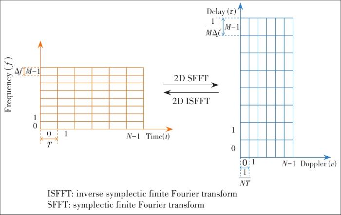
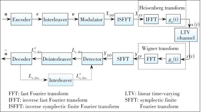
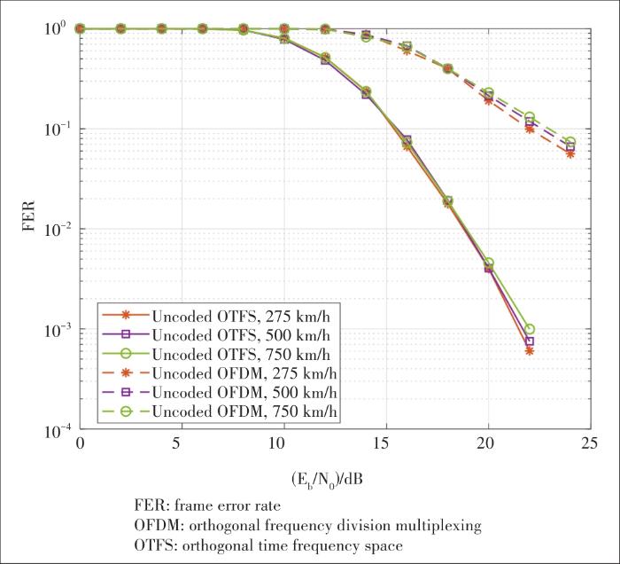
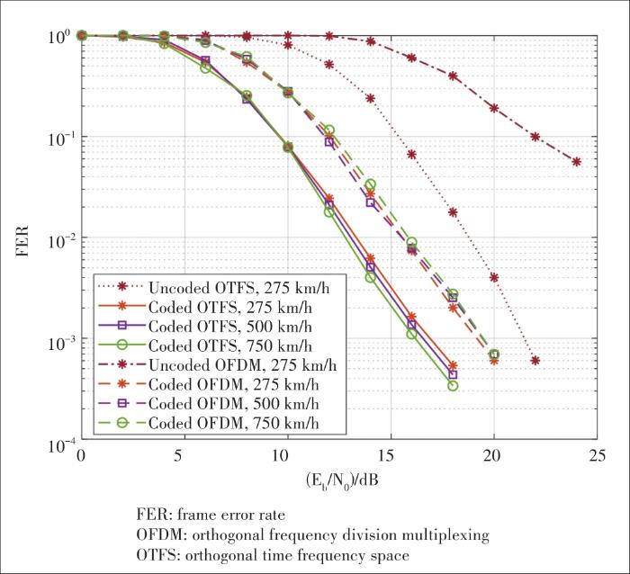
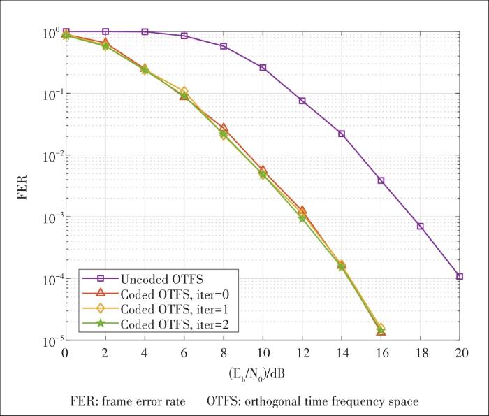
